What Happened #
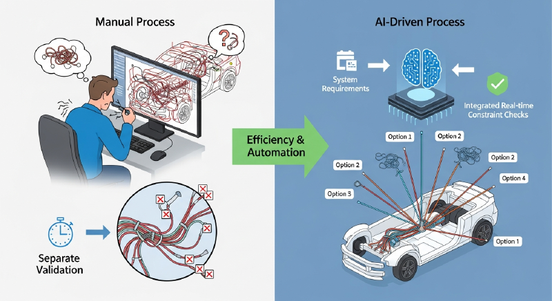
The rapid rise of electric vehicles (EVs), autonomous driving, and urban air mobility (UAM) has caused an exponential increase in the electronics packed into modern vehicles. As a result, wiring harnesses — the nervous system connecting every electrical component in a car or aircraft — have reached staggering levels of complexity. Traditional harness engineering required engineers to manually trace 3D routing paths in CAD software based on 2D schematics, checking physical and electrical constraints one by one. It was intensely labor-intensive work.
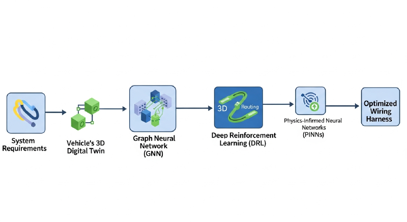
Over the past few years, major CAD vendors like Siemens, Dassault Systèmes, and Zuken, alongside AI startups in the manufacturing space, have begun integrating generative AI into harness engineering. This goes far beyond tidying up existing wire paths. Engineers now input system requirements — such as “connect sensor A to controller B with these current tolerances and communication specs” — and the AI analyzes the vehicle’s 3D digital twin to automatically generate optimal wiring topologies and 3D routing paths. This technology is moving into real production use.
The impact is significant: design cycles that previously spanned months are being compressed into days or hours, and the AI uncovers optimization opportunities that humans routinely miss, delivering dramatic reductions in total cable weight and cost.

Why It Matters #
The wiring harness is the third-heaviest and third-most-expensive component in a vehicle, after the engine (or battery pack) and chassis.
- Breaking the weight and cost barrier: In the EV era, reducing weight is essential for maximizing range. AI can search across millions of routing combinations to find the shortest safe path — cutting copper usage and directly lowering both cost and vehicle weight.
- Automating complexity management: As autonomous driving capability increases, so does the density of high-speed data cables for sensor processing. When power lines and communication lines run too close together, electromagnetic interference (EMI) becomes a real problem — one that is nearly impossible for humans to anticipate and avoid across an entire 3D space. AI models can consider all of these multi-dimensional constraints simultaneously when generating a design.
- A paradigm shift in engineering software: From a developer and software architect perspective, this is not merely a “new feature.” It represents a fundamental replacement of the core engine — from traditional rule-based geometric computation (e.g., shortest-path search via Dijkstra’s algorithm) to data-driven probabilistic generative models and reinforcement learning agents.


Technical Analysis #
Harness engineering AI generation systems rest on three technical pillars: Data Representation, Topology Generation, and 3D Spatial Routing.
1. Data Representation: Graph Structures #
A harness system is fundamentally a graph — nodes (connectors and splices) connected by edges (wires and bundles). To help AI understand this, Graph Neural Networks (GNNs) are the predominant approach.
- Node Features: Connector pin count, voltage/current ratings, position coordinates, thermal resistance limits.
- Edge Features: Wire gauge (AWG), shielding status, length, flexibility.
GNNs train on databases of successful historical harness designs, learning to infer which graph topology is most stable and efficient for a given system architecture.
2. 3D Spatial Routing: Deep Reinforcement Learning (DRL) #
Once the logical 2D circuit is defined, it must be physically routed inside the real 3D structure — a vehicle body or aircraft frame. This is where Deep Reinforcement Learning delivers its strongest results.
An agent explores the 3D space to build routing paths, receiving rewards or penalties from its environment.
- State: The path routed so far, remaining target points, 3D voxel data or point cloud of surrounding obstacles (vehicle body parts).
- Action: Direction and length of the next path segment (x, y, z vector).
- Reward Function:
- Large reward upon reaching the target.
- Additional reward for shorter paths.
- Penalties: Collision with obstacles, minimum bend radius violation, proximity to heat sources (engine, exhaust), clearance violations between power and signal lines.
Below is a Python-based pseudo-code example of how a DRL environment is structured.
|
|
3. Validation and Optimization: Physics-Informed Neural Networks (PINN) #
To verify that a generated path is physically sound, PINNs (Physics-Informed Neural Networks) are increasingly being applied. Traditionally, finite element analysis (FEA) was used to simulate cable sag and vibration-induced wear — at very high computational cost. By embedding physical laws directly into the loss function during training, PINNs allow the AI to propose physically valid paths in near-real-time, starting from the generation stage itself.

What Changed #
| Category | Traditional Harness Engineering (Rule-based / Manual) | AI-Generated Harness Engineering (Generative AI) |
|---|---|---|
| Design Method | Engineers manually draw 3D splines from 2D schematics | AI auto-generates and proposes multiple 3D routing alternatives from system requirements |
| Path Search Algorithm | Simple shortest-path search via Dijkstra or A* (limited multi-constraint support) | DRL-based, simultaneously handling thermal, EMI, vibration, and other compound constraints |
| Design Change Response | Full manual re-routing required when body structure changes | Recognizes structural changes and auto-reroutes in real time |
| Validation | Batch validation via separate analysis tools after design completion; redesign loop on error | Constraints are embedded as reward functions during generation, achieving Correct-by-Construction |
| Knowledge Capture | Dependent on individual veteran engineer experience and judgment | Learns from historical design data (PLM/CAD) to encode company design expertise as model weights |

Implications for Developers #
As AI becomes embedded in the harness engineering ecosystem, software developers and data engineers in this space face a new set of requirements and opportunities.
-
Mastering CAD API and Plugin Development An AI model running in isolation has no practical value. Its output must be immediately applicable inside commercial CAD tools like CATIA, NX, or AutoCAD Electrical. Developers need to work with complex vendor-provided APIs using C++, C#, or Python, and design smooth plugin (add-in) architectures that bridge an AI backend server to a CAD frontend.
-
Building Pipelines for Unstructured Legacy Data Training AI requires historical design data — but most manufacturing data is fragmented across formats like XML, PLMXML, STEP, and IGES, often containing human errors. Developers must build robust data pipelines that parse this heterogeneous CAD data, remove noise, and convert it into structured graph or tensor data suitable for training GNN or DRL models.
-
Real-Time 3D Rendering and Inference Optimization Having an AI agent search routing paths and render inference results in real time within a 3D assembly of tens of thousands of parts demands enormous computing resources. Lightweight 3D visualization using WebGL or OpenGL, combined with inference speed optimization via ONNX or TensorRT, becomes a core development challenge.
-
Fusing Domain Knowledge into Code Beyond pure software engineering, the ability to model mechanical constraints (bend radius, tension limits) and electrical constraints (voltage drop, EMI) in code becomes essential. Collaborating closely with domain experts to translate physical equations into AI loss functions or reward functions is an increasingly critical design skill.

Looking Ahead #
In the near term, “copilot” style adoption will dominate. Rather than full automation, the prevailing model will be human-AI collaboration: the engineer specifies start and end points, the AI proposes 3 to 4 high-quality routing options, and the engineer selects and fine-tunes the result. This will become a standard feature in CAD software. For developers, it highlights the importance of designing interfaces that integrate AI suggestions naturally without disrupting the existing UI/UX.
In the medium to long term, the industry is moving toward fully automated requirements-to-design generation. Given only high-level inputs — a text description or a system block diagram — AI will automate the entire pipeline: from logical circuit design to 3D routing, to generating nailboard 2D drawings and extracting a bill of materials (BOM). Beyond that, combined with digital twin technology, the system will simulate vibration and thermal changes as the vehicle operates in virtual space, enabling harness designs that evolve and self-optimize — what some are calling evolutionary design.